11/2000
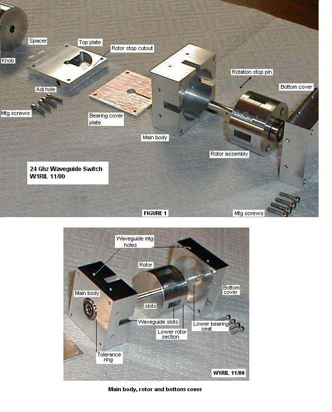
The WR42, 24 Ghz, 4 port transfer switch is made up of several machined parts. The parts in figure 1 from left to right are: knob, tfe spacer, top plate, bearing cover plate, main body, rotation stop pin, rotor assembly, and bottom cover. The rotor consists of an upper section with shaft and rotation stop pin and a lower section. Both upper and lower sections are fitted with ball bearing races. The upper section contains the arched waveguide slots on its bottom surface. The lower surface of the waveguide slots are formed by the addition of the lower section. Slots in the control knob, similar to those in the rotor, indicate the passages through the 4 ports of the switch.
| 1 Pc | 6061T6 Aluminum plate 3/4" X >1.5" square |
| 1 Pc | 6061T6 Aluminum plate 1/2" X >1.5" square |
| 1 Pc | 6061T6 Aluminum plate 0.060" X >1.5" square |
| 1 Pc | 6061T6 Aluminum plate 1/4" X ~1-1/4" X ~ 1-3/4" (for jig) |
| 1 Pc | 6061T6 Aluminum rod 1-1/4" dia X 3-1/4 long |
| 2 Ea | Bearings (from defunct computer hard drive)
ID ~ 0.193", OD ~ 0.512, Thickness 0.156" |
| 8 Ea | Socket head cap screws, SS, 2-56 X 3/8" long |
| 2 Ea | Pan head screws, SS, 2-56 X 3/8" long |
| 3 Ea | 4-40 allen head set screws |
| 3 Ea | Flat head screws, 4-40 X 3/8" long (for jig) |
| 1 Ea | Pin 0.040" dia X 0.665" long |
| 1 Ea | Tolerance ring (may or may not be needed - see text) |
| 1 Ea | 4-40 hex head nylon nut & bolt 3/8" long |
PROCEEDURE:
Make facing cuts on both ends of the 1-1/4" OD aluminum bar and a 0.005 cut across the outside diameter to clean up and smooth the outer surface. This is cut into three pieces using a cutoff tool in the lathe. Cut off pieces to be finished to 3/4" long, 5/8" long and the remaining section approximately 1- 7/16" long. Make facing cuts on each rough end and finish to size with the exception of the 1-7/16" long piece which will be left long for now. This will be the rotor and will receive the waveguide cuts and upper bearing. The remaining length will become the rotor shaft. The 3/4" section will be the bottom of the rotor, forming the bottom of the waveguide slots and holding the lower bearing race. The remaining 5/8" piece will be used for the control knob.
Machine the 3/4" thick piece of 6061T6 aluminum to 1.5" square. It is important that it be exactly 1.5" on each side, and square. Waveguide slots will be cut in the exact center of all four sides after machining for the rotor and upper bearing. Cut the 0.060, 1/4", and 1/2" aluminum 6061T6 pieces to1.510" square. Make a cleanup cut on the top and bottom faces of the 1/2" and 3/4" blocks. Usually a couple of thousandths cut with the flycutter will clean and smooth the surfaces really well. The 1/4" block will be done later after machining the rotor stop cutout. The 0.060 bearing cover plate I used was as anodized piece and did not require further finishing.
On all of the squared up pieces, find, and using a center drill, mark the exact center of each. Drill a pilot hole thru each with the exception of the 1/2" block. On this piece locate the center and drill the pilot hole only to a depth of 1/4" on one surface only.
SELECTING THE BEARINGS:
An old defunct 100 MB computer hard drive contained two bearings with the following dimensions: ID 0.198, OD 0.512, Thickness 0.156. If you use bearings of different dimensions appropriate changes will have to be made in the bearing seats, shaft diameter, etc.
MAIN BODY:
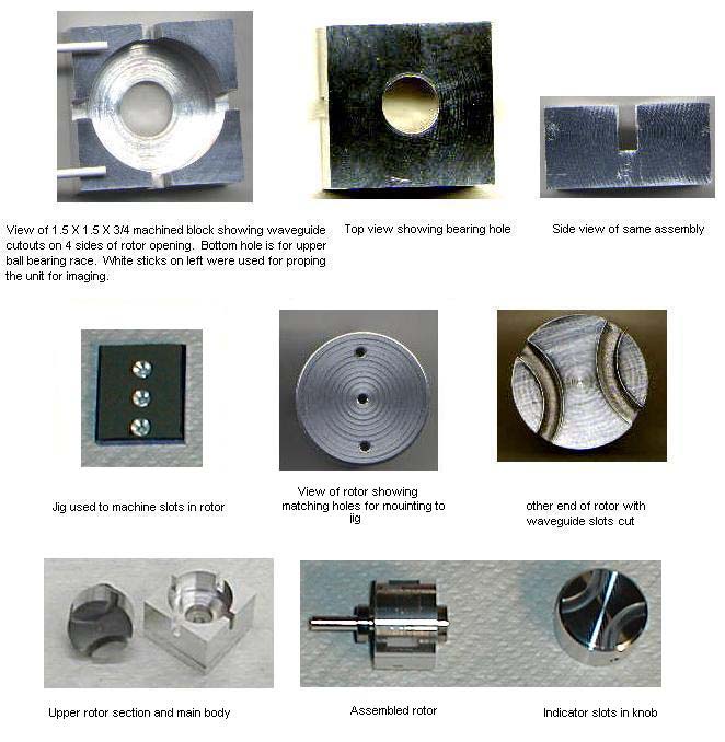
Open the center of the 3/4" block with a 1/2" drill. Chuck block in lathe, center up and enlarge the 1/2"hole with a boring bar to except the bearing with a push in fit. It should be snug but removable with moderate pressure. On one face of this block enlarge the hole to except the 1.240" rotor to a depth of 0.594". (The block thickness minus the bearing thickness 0.750 - 0.156 = 0.594) If your bearings are different change both of the above operations accordingly. Open the rotor hole in the main body until the rotor just fits. It should turn easily with no binding.
Mount the block in the milling machine with the large rotor opening at the top. Cut the waveguide slots, 0.420" deep and 0.170" wide, centered on each of the four sides. Clean up the edges after machining.
ROTOR: Insert the rotor into the main body cavity and mark where the rotor is flush with the top of the block. On the opposite end drill a center hole in the rotor and tap for 4-40 screw approximately 1/4" deep. This area of the rotor will be cut down to the ID of the bearing and shaft after the waveguide slots are cut.
Using the piece of 1/4" X 1-1/4" X 1-3/4" aluminum plate make a jig for machining the rotor slots. Machine the 1-1/4" dimension to the exact diameter of the rotor body. (~1.240") Mark off a square area at the end of the plate 1.240" by 1.240" and locate its center. Put the plate in the milling machine and using a center drill locate the center hole and two other holes 0.425" in line with and on opposite sides of the center. Drill a pilot hole with a #55 drill at these three locations. Open the center hole to just clear a 4-40 screw and countersink one side so screw head will be just under flush with surface. Mount rotor to this plate with a 4-40 FH screw. The outside edges of the rotor should be flush with the plate edge on three sides. With the #55 drill locate the other two holes in the rotor. Remove from plate and drill and tap both holes for 4-40 screws. Drill out and countersink the two remaining holes in plate. Mount the rotor to the plate securely with three 4-40 flat head screws.
Mount the rotary table, set at "0" degrees, on the milling machine and locate the headstock to the center of the table. My rotary table has two "T" slots on it that divides the top into 4 equal segments. The slots are 0.248" wide. One half of the slot is 0.124". Set the jig, with rotor attached, in the lower right corner of the upper left quadrant of the table. Align to leave 0.124" on the "X" and "Y" axis of the "T" slots showing. The lower right corner of the jig should be at the table center. Clamp the corners of the jig securely to the table and set the cutter well above the rotor. Dial in 1/2 the rotor diameter on the "Y" axis. This puts the cutter in the center of and to the right side of the rotor. Back the cutter off a few degrees by turning the rotary table and bring the cutter down to the material. Cut the 90 degree arc in the surface of the switch rotor to a depth of 0.420". Check width and cut each side equally to a width of 0.170" maintaining the 0.420" depth. Remove the jig with rotor attached from the milling machine and rotate the rotor 180 degrees on the jig. Align as before and repeat for the slot on the other side of the rotor.
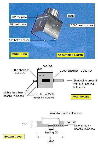
Remove jig and rotor from rotary table and remove the three screws holding the rotor to the jig. Insert the rotor into the main body block and recheck the depth line on the rotor previously made. Chuck the rotor in the lathe with the waveguide slots facing toward the chuck. Reduce the diameter of the exposed end to the depth line to 0.250". Leave a 0.002 segment next to the rotor and reduce the remaining shaft for a tight fit to the ID of the bearing. As before, if using different bearings, adjust dimensions accordingly. See rotor drawing.
Clean up rotor slot edges and insert the rotor shaft up thru the bearing seat hole in the main body. The lower edge of the rotor should be flush with the bottom of the main body and when rotated the rotor waveguide cuts should line up with those on the four sides of the main body. If problems occur with upper bearing alignment the bearing seat can be opened and a tolerance ring installed. 1 This will adjust for minor misalignments in rotor and bearing seats. Make sure "no drag rotation" is possible to at least two slots. If complete rotation is possible so much the better, however only 90 degrees of rotation will be necessary on final assembly.
TOP PLATE AND BEARING COVER PLATE:
Open center holes in the top plate and bearing cover plate with a #7 drill. Locate and drill pilot holes in the top plate, bearing cover plate and the top corners of the main body. These are to be 0.125" in from each edge in all four corners. Drill the top plate first and use as a template for the other two. Open the top plate corner holes for clearance of 2-56 screws and countersink the cap screw heads using a larger drill to 0.125". Drill and tap the corner holes in the top of the main body for 2-56 screws to a depth of 0.250".
BOTTOM COVER:
Locate and drill pilot holes in the four corners of the 1/2" block 0.125" in from each side. Drill all the way thru the block. Chuck block into lathe with the previously located center drilled side facing away from the chuck. Extend the center hole with a pilot drill to a depth of 0.400". Open hole with a 1/2" drill to this same depth, 0.400". Use the boring bar and open hole to ~0.510 for the lower bearing seat. This should be a snug fit. Leave 0.165" for the bearing seat and clearance and open outer 0.235" of hole to rotor diameter, 1.240". See pictures.
LOWER ROTOR:
Fit lower rotor section into the bottom cover, mark and turn to bearing ID. Leave 0.002" X 0.250" diameter shoulder for clearance. Cut shaft to 0.152" long and press bearing onto shaft. Drill two pilot holes with #55 drill for mounting to the upper rotor section. Place lower rotor section on bottom of upper rotor and locate holes. Drill and tap for 2-56 screws. Countersink heads in lower rotor at just below flush with rotor bottom. Using previously drilled pilot holes in bottom cover, align, locate, drill and tap 2-56 corner holes in bottom of main body to a depth of ~ 0.300".
PREASSEMBLY AND CLEANUP:
Assemble rotor into main body and attach bottom cover and both top and bearing cover plates. Assure no drag rotation of rotor and snug up top and bottom mounting screws. Mount assembly in milling machine and with the fly cutter take a cut of 0.006 to 0.010" to get all plates and main body flat and even on all four sides. Using a prick punch make a witness mark on the upper corner of each plate on one side for future alignment. Flycut the bottom of the bottom cover for a clean smooth surface. Disassemble and remove top plate. Clean off top surface of top plate with fly cutter. On the bearing cover plate cut a 0.0625" slot centered on the center hole the length of the stop pin. This enables removal of the plate when the stop pin is installed in the rotor shaft. Once the stop pin is installed the rotor cannot be removed from the body without removing the pin. Locate the pin location on the shaft to fall in center of the thickness of the 1/4" top plate. Drill hole in shaft. The pin I used would just go thru a drill gage #59 hole. The shaft hole was made a #60 and the pin was pressed in. If you have trouble locating a pin a #59 drill shank will fill the bill nicely .
Locate a 90 degree segment, plus one half the diameter of the stop pin on the bottom side of the top plate for removal. Make sure of its location relative to rotor rotation if rotor only turns freely through a 90 degree segment. You don't want the 90 degree area to be where the rotor binds when the witness marks are aligned on assembly. Mill out this area to a depth of 0.215 to 0.220". See picture. Locate holes for end of rotation stops and drill #43 hole for taping with a 4-40 tap. Open clearance hole for the tap body to a depth of 0.500" with a #27 drill. Tap holes and insert 4-40 Allen head set screws flush with the 90 degree cutout edge. They will be adjusted later on final assembly.
WAVEGUIDE MOUNTING HOLES:
Remove the rotor assembly from the switch. Put the bottom cover back on and snug up the screws. Using a piece of hardwood (maple) shape a rectangular piece to the size of the internal dimensions of WR42 waveguide and about 2" long. Insert this through two opposite holes in the switch body. Lay the body on the workbench with one side down and the hardwood protruding through the waveguide slot on the top. Place a waveguide spacer (this is a block of metal with waveguide cutout and 4 mounting holes bored through it) on the exposed hardwood flush to the side of the switch body. Using a #32 drill bit with the shank end ground to a point insert the drill shank end into each of the 4 holes in the waveguide spacer and tap lightly with a piece of wood. Repeat this process until all four sides of the switch body have mounting hole locations around its waveguide slots. Prick punch these 16 holes and drill to a depth of 0.200" with a #50 drill. Do Not penetrate the rotor cavity wall - use caution. Tap all holes with a starter tap followed by a bottoming tap.
KNOB:
With the remaining 5/8" piece of 1-1/4" diameter aluminum make the knob. Locate and drill the hole for the rotor shaft. Drill and tap the side of the knob for a 4-40 Allen set screw. Mount knob on rotary table and make two 90 degree cuts about 0.010 deep on the knob top. These are used to indicate connecting ports on the switch. See picture. Cut a small 1/2" doughnut from 0.005" teflon sheet to be used as a spacer under the knob.
ROTOR ATTENUATION SLOTS AND FINAL ASSEMBLY:
Mount rotor onto milling machine and with a slitting saw cut 0.010 slots in the rotor parallel to the long dimension of the waveguide openings. These are located 0.125" on each side of the waveguide openings and are 0.125" deep. They are cut the entire length of the rotor.
In the bottom cover drill a center hole with a number 43 drill. Tap this hole using a 4-40 tap and install the nylon hex head bolt with nut attached up thru the bottom hole. The nylon bolt is used to put friction on the rotor to prevent accidental movement when switching from one position to the other. The nut is used to lock the bolt in position. This bolt assembly is not shown in any of the drawings as it was added when it was noted that the switch could get offset from the desired position too easily!
Clean all pieces thoroughly and wipe down with a solvent such as lacquer thinner. Assembly rotor into main body and press stop pin into shaft. Install bottom, bearing, and top covers and secure mounting screws. Place spacer and knob on shaft. Adjust indicator slots to the switch position and tighten the knob set screw. Check rotation and adjust set screws for proper rotational stops. Adjust the nylon bolt in the bottom cover for slight frictional binding of the rotor movement and tighten the lock nut.
FINAL COMMENTS:
If you are a machinist by trade this probably took you much less than the 60 hours that it took me. The end results are however well worth the time and effort.
NOTES:
Tolerance rings are available from Small Parts Inc. Miami Lakes, FL 33014-0650
Cross-talk between the two circuits is less than -45 dB (which was just at the limit of the test equipment setup).
The information contained on this page is provided for amateur radio interests. It may be copied for those purposes only. If copied and reproduced for this purpose, this statement must also be copied and reproduced. This material was authored by W1RIL and presented at http://www.wa1mba.org/