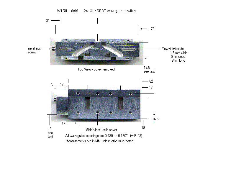

This waveguide switch
is made from a square piece of 3/4 inch
rectangular aluminum stock having 1/8 inch walls and a solid
piece of aluminum approximately 1/2 inch x 5/8 inch x 2-5/8 inch.
The latter is used as the moving portion and does the actual
switching of the ports.
Not being a machinist by trade I am sure there are better and more efficient ways of building the switch. The procedure I used in construction is as follows.
Start with the 3/4 inch square 1/8 inch wall aluminum and size to 62mm long . Square up both ends. Open one side by removing center material to make a "U" channel leaving the outside walls intact. Mill both inside edges flush with the existing internal walls.
Locate and mill out the 3 waveguide cutouts in the "U" channel. Remove any burrs left from machining with a fine file keeping all edges clean and sharp.
Machine the 1/2 X 5/8 X 2-5/8 block to be a smooth sliding fit into the "U" channel. Place the block in the channel and check for clearance with the cover in place. Refine the height as required. The block should slide back and forth in the channel with no binding and virtually no side play. Cut the block to 73mm long and square up the ends.
Place the block in the "U" channel and slide it so the end of the block and channel are flush on one end. Locate and mark the location of the two waveguide cutouts onto the block. Slide the block flush with the opposite end and likewise locate and mark the waveguide cutouts onto the block. With a square transpose the markings on the side to the top edges. Mill out the slots to the proper waveguide dimensions. The diagonal slot connecting the in/out openings is approximately 3 - 1/4 Xg lengths long at 24.192Ghz. This tends to cancel errors produced by the corners. Locate and mill out the two travel limit slots on the sliding block.
Locate and install pin stops in the top cover. I used small SS pins pressure fit into undersized holes in the cover. A 2/56 machine screw is located on one end of the sliding block to allow small adjustments for alignment. One could be used on each end of the slide if desired. This may be necessary depending on how accurately the travel limit slots and pin stops are located.
The dimentional drawing also shows two additional slots in the sliding block which put a load on the idle port. Absorbing material was glued to the rear of the slots as loads. How effective these are is not known as no tests were performed on them. Any device (amp., LNA - etc) would normally be powered down in that switched state in most cases.
W1GHZ ran some tests on the switch and found the VSWR to be 1.45 and 1.55. Isolation 35 to 45 dB, and loss very close to zero. The VSWR with the output shorted was ~600.