Above is a diagram of the power head components. An actual photo is below.
Several people have asked me if it is possible to repair an HP 478A-style thermistor mount (Power Head for 431 / 432 power meters). Surprizingly, in SOME cases the answer is YES!
The first step is to do triage - figure out if the head is completely fried. Some of these heads will withstand 1 watt for 10 ms and appear broken, but can be brought back to life.
The only way to tell if a thermistor resistance is in specifications is to measure the resistance under simulated operating conditions. This is complicated and I outline how to do it at the end of this message.
In the case of a power head that pins the power meter (one way or the other) you don't care about resistance being within spec - IT ISN'T. What you do care about is whether it is totaly fried or can be brought back. Use a good digital ohmmeter on the 20K scale so that it draws very little current. Don't leave the meter connected for more that a second or two. The absolute maximum curent that a thermistor can take is 13 mA. If you are unsure about the current that your meter provides, set it to a 20 K scale, and connect it in series with a 1 K resistor and a milliameter. If there is more than 10 milliamps, the meter might damage the thermistor.
To determine if it is reparable, measure the resistance between pins 1 and 2, and also between 3 and 4. The resistance should be between 1000 and 5000 ohms.
If you read an open or a short, you have blown thermistors, and might as well trash the unit. If they are both about 1K to 5K, proceed to repair/adjust.
Don't forget to check the cable... if there is an open, or a faulty connection, this can cause the same symptoms as a bad head.
1. Take the can off the N connector by removing three set screws. Slide the cover can off.
2. Plug the unit into your 431 / 432.
3. Set the resistor mount ohms to 200 (assuming you are reparing a standard 478A - some of the microwave heads are 100 ohms, so set the control accordingly).
4. Turn the power on.
5A. If the meter is pegged down scale
a. set Range to 10mW
b. Set ZERO and VERNIER to mid-range (on the 432, carefully count the turns of the screw-driver coarse- zero pot and set it to mid range)
c. on the back of the thermistor mount there are two small brass screws. Take your time. Turn one of the screws 1/8 (yes 1/8) turn clockwise. Then turn the other screw 1/8 turn clockwise.
If there is a sudden jump in meter indication when advancing either screw, back it off 1/8 turn, and do NOT advance that screw any further. If either screw bottoms, do not apply force - it is likely that if a screw bottoms, the thermistor is fried.
d.The best result is when at some point in the alternating "turning of the screws" the meter rises. Once it starts to rise, trim it to zero by turning each screw a little.
5B. If the meter is peggged upscale,
a. Set meter to Zero (as in 5A above step b)
b. Set RANGE to highest power position which will not peg the meter.
c. Turn one of the little brass screws CounterClockwise (leftwards or anti-clockwise in the Queen's English) to obtain a meter reading of half the deflection noted in step b.
d. Turn the other screw CounterClockwise to zero the meter. If it is impossible to zero the meter, at least one of the thermistors is fried.
6. Replace the cover. Congratulations! the head works, is no longer calibrated, but is probably within one dB of its original calibration. Check it with a known good source or another meter to get a calibration factor.
Note. Some waveguide type units have only one adjusting screw. Follow approximately the same procedure, adjusting only the one screw.
Above is a diagram of the power head components. An actual photo is below.
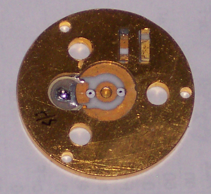
Above is a photo of the innards of the 478 head. Thanks to Francois, F1CHF for this photo. The two sensing thermistors are very small black dots either side of the very center. They have very thin horizontal leads. The two reference thermistors are (about) impossible to see in this photo. They are attached across the two ceramic and gold vertically oriented blocks in the upper right powertion of the photo. They are shown in the diagram above. The blob of solder to the left of the sensing thermistors is where the coupling capacitor hides.

Above is a schematic of the power head thermistor wiring.
Above is a diagram of the power head pins.
If you really want to check a mount for thermistor match you need a 29V DC power supply, a second high resolution supply with floating terminals adjustable 2 to 3.1 V, a switch, a 2200 Ohm resistor and a millivolt resolution digital volt meter. You set up this circuit and adjust the adjustable supply as a bucking voltage to get a very small reading on the volt meter and then swtich between the two thermistors to make sure that the readings do not vary by more than .030 volts. Non-opearating units with readings as high as .150 difference can usually be repaired per instructions. I don't recommend that you do this, first of all, its not usually necessary, and second of all, if you get it wrong you can fry the thermistors.
Above is a schematic of the power head test setup wiring.
Here is a message from Brian Kline, WA6QDP from a microwave email reflector post
I agree with Jeff.
The early manual for the 477 thermistor mount (used with the HP 430 power
meters) lists the thermistors used in it as Veco 32A5 or W.E. #170575.
I suspect that 478 uses a set of four of these matched to produce close to
100 ohms resistance each with the same drive power. Two in the temp
compensation leg and two in the RF measurement leg.
The Veco 32A5 spec is
| Parameter | Value |
| Zero-Power Resistance Ro @ 25C: | 2,000 ohms ±25% |
| Temperature Coefficient a @ 25C: | -3.4 %/C |
| Ratio (Ro @ 0C)/(Ro @ 50C): | 5.6 |
| Ratio (Ro @ 25C)/(Ro @ 125C): | 14.6 |
| Time Constant: | 1 second |
| Dissipation Constant: | 0.1 mW/C |
| Special Features: | Controlled resistance within a specified current range |
| Diameter: | 0.013" |
| Leads | .001" DIA platinum-iridium |
YSI currently lists the 32A48, and 32A50 which have similar specifications
in their catalog. I suspect you would need to select these for a matched set
of 4 for the 478.
The 42A29 from BG Micro is in many ways similar, but to get the 100 ohm
resistance in the bridge you would need to dissipate excessive power in the
thermistor, or parallel a bunch which would increase the dissipation
constant to an unreasonable value.
Brian
WA6QDP
Further reading on the operation of the 431 power meter is available by
Pressing here. Thanks to KK6MK and others.
This page is brought to you by WA1MBA
Almost everything here was found other places on the web or donated.
If you have a comment, please
send me mail at .
.
This page last updated 8/13/17
Thanks to Mike WA4HFR for pointing out an error in the schematic!